Creating a Pick and Place Control Board with the RP2024
페이지 정보
작성자 Kennith 댓글 0건 조회 56회 작성일 24-05-22 22:43본문
RC0 - RC3 used as inputs to read in the SMINI baud rate DIP switch segments. RA0 - RA5 used as inputs to read in the SMINI Address DIP switch segments A0 - A5. It also keeps track of which information is data and which is address and determines when to activate each of the port enable lines for communication with the SMINI’s 9 different I/O ports - 3 for inputs and 6 for outputs. The functional blocks, noted as U9 through U13, perform as buffer/line-drivers for the 6 output ports. RC5 used as output to drive the transmitter enable line for enabling the RS485 transmissions from SMINI back to the PC. In the picture above, the general network topology of RS485 is shown. And, of course, the installation can make or break the network performance. An advantage is that this allows the software (if properly written) to take control of the network and hold it for a short time before transmitting the data. Now being used commonly in the pro audio industry to control digital audio and signal processors such as the DBX driverack and other manufacturers equivalent products. Implementing this requires a higher level addressing scheme so the data being transmitted goes to the correct device.
Besides being more than twenty times faster and much more powerful than the MC68701 used in the original design USIC, the programmed PIC16F877 is about half the cost. Programming the PIC16F877 FLASH memory requires a special PIC Micro Programmer package. Do not worry about having to do any PIC programming. As a bare minimum the package needs to include a programming editor and an assembler that turns the user written assembly language code into 1s and 0s for loading into the PIC16F877 Microcontroller. On the serial side of the SMINI, one of two special I/O circuits couples the PIC16F877 to the serial I/O lines coming to SMINI from the main computer, the PC. Most functions are handled directly by the PIC16F877 including all the parallel-to-serial and serial-to-parallel conversions and determining the operational timings for both the serial and parallel lines. The SMINI has six 8-bit output ports labeled as Ports A, B and C for "Cards 0 and 1." Similarly, the three 8-bit input ports are labeled as Port A, B and C for "Card 2." Each I/O port includes an important buffer between the railroad’s connection to the SMINI card and the PIC16F877.
Its main hardware functions are address decoding, baud rate generation, parallel-to-serial and serial-to-parallel conversion, input/output port selection, input port buffering and output port latching. RC4 used as input to read in the SMINI address DIP switch segment A6.ตัว Converter สามารถ Auto Selectable Baud Rate ให้อัตโนมัติ , ด้าน RS485 มีขั้วต่อให้เลือกใช้ได้ทั้งแบบ สกรูขัน(Terminal) หรือ ขั้ว RJ-11, สามารถใช้งานเป็น Converter RS232 to RS422 ได้โดยการสลับ Dip Switch ภายในกล่อง , Converter ตัวนี้ผ่านการทดสอบ การใช้งานภายในโรงงานอุตสาหกรรมมาแล้วเป็นอย่างดี(Industrial Specification).
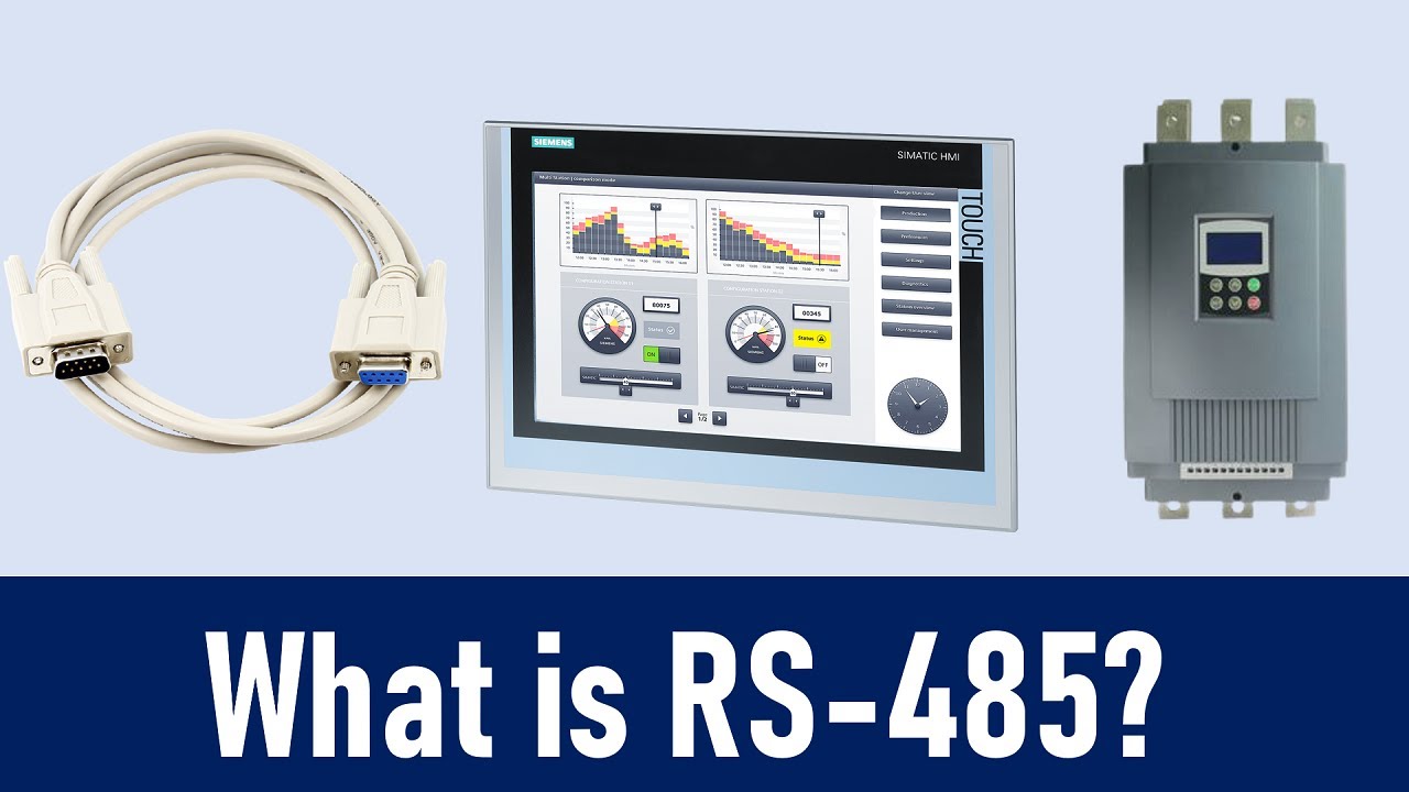
Common standards: RS232 RS422 RS449 RS485 20 mA current loop RS485 was developed to provide high speed data. RS485 is the most versatile communication standard in the standard series defined by the EIA, as it performs well on all four points. This provides some noise immunity as well as resolves the problem of missing the start bit, but only for the receivers that implement this internal biasing. Shielding-which is a common method to prevent noise in RS232 lines-tries to keep hostile magnetic fields away from the signal lines. This way, the lines will be biased to known voltages and nodes will not interpret the noise from undriven lines as actual data; without biasing resistors, RS485 standard the data lines float in such a way that electrical noise sensitivity is greatest when all device stations are silent or unpowered. All of the application guides and data sheets that say RS-485 has a limit of 1200 meters or 10Mbit are flat out wrong. RS-232 only defines connecting DTE to DCE, so when two computers are connected together this is outside of the standard. This document is primarily directed at discussion of RS-485 but also includes information about RS-232 and RS-422.
- 이전글010388.com 슬롯 무료체험 사업자의 시장 지배력 남용을 방지하기 위해 마련한 DM 24.05.22
- 다음글타다라필 운동【 SKYWINPC77。COM 】씨알리스 처방 24.05.22
댓글목록
등록된 댓글이 없습니다.